Property Sockets
Property sockets are part of a Node Graph system. If you are not familiar with the Node Graph, we recommend you to read the Getting Started with Nodes guide first.
What are Property Sockets?
Section titled “What are Property Sockets?”Each Node consists of 2 things: inputs and outputs.
Inputs are on the left side of the Node, and outputs are on the right side. Each input and output has a type, which defines what kind of data it can accept or produce.
Inputs
Section titled “Inputs”Inputs can be in 2 states. Connected or disconnected. Disconnected inputs usually expose a value editor to the user, allowing them to change the value of the input.
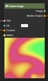
Connected Size input does not expose anything. It’s value is determined by the output of the node it is connected to. You can preview the value of the input by hovering over the socket.
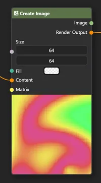
Disconnected Size input exposes two number inputs.
Outputs
Section titled “Outputs”Outputs are always in a connected state. They produce data that can be used by other nodes. Outputs can be connected to inputs of other nodes, allowing you to create complex graphs.
Property Types
Section titled “Property Types”Each property holds/can process a specific type of data. Each data type is represented by a specific color:
⬤ Painter
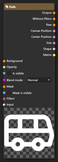
Section titled “⬤ Painter”A painting operation, each Node that accepts a Painter either connects to the chain of painting operations or paints the chain of operations to the texture.
The simplest example are layers and the Output Node. Each layer accepts a ⬤ Background input and returns a Output ⬤.
While the Output Node accepts a ⬤ Background input and does not return anything.
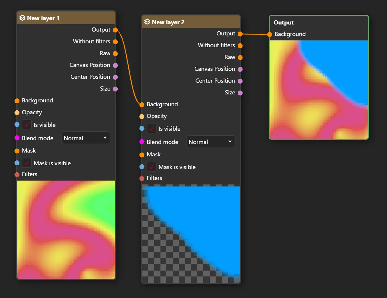
In that example, chain of 2 painting operations is created.
- Paint the “New layer 1”
- Paint the “New layer 2” on top of the first layer with blend mode “Normal” and opacity 100%.
Output Node then takes the result of the chain and displays it in the viewport.
⬤ Texture
Section titled “⬤ Texture”A texture with defined width and height. For example Create Image Node produces a ⬤ Texture output, which can be used by other nodes that accept textures, such as the Modify Image Node.
⬤ Filter
Section titled “⬤ Filter”Filter object that can be applied via the Apply Filter Node or directly to the layer. Filters can be used to modify the appearance of the texture, such as applying a blur or a color adjustment.
⬤ Boolean
Section titled “⬤ Boolean”A boolean value, which can be either true or false. Value 0 is equal false, and any other value evaluates to true.
⬤ Float
Section titled “⬤ Float”A floating point number, which can be used to represent decimal values. It occupies 4 bytes of memory and can represent values from approximately ±1,5 x 10−45 to ±3,4 x 1038
⬤ Double
Section titled “⬤ Double”A double-precision floating point number, which can be used to represent decimal values with higher precision than a float. It occupies 8 bytes of memory and can represent values from approximately ±5,0 x 10−324 to ±1,7 x 10308
⬤ Color
Section titled “⬤ Color”A 32-bit ARGB unpremultiplied color value.
⬤ Paintable
Section titled “⬤ Paintable”Paintable is a type that describes fill/brush. Color is a paintable, it describes a solid color fill. Another type of paintable is a Gradient, which describes a gradient fill.
⬤ VecD
Section titled “⬤ VecD”(Vector 2 of double precision numbers)
A vector with 2 double precision numbers.
⬤ Vec3D
Section titled “⬤ Vec3D”A vector with 3 double precision numbers.
⬤ VecI
Section titled “⬤ VecI”A vector with 2 integers.
⬤ Integer
Section titled “⬤ Integer”An integer value, which can be used to represent whole numbers. It occupies 4 bytes of memory and can represent a number from range: -2,147,483,648 to 2,147,483,647
⬤ String
Section titled “⬤ String”A string value, which can be used to represent text.
⬤ Ellipse Data
Section titled “⬤ Ellipse Data”(Vector Shape)
An ellipse data type, which can be used to represent an ellipse shape. Properties of the ellipse data type are:
Center(VecD)Radius(VecD)
⬤ Points Data
Section titled “⬤ Points Data”(Vector Shape)
A list of points (VecD).
⬤ Text Data
Section titled “⬤ Text Data”(Vector Shape)
A text shape data type, which can be used to represent a text shape.
Vector Shape
Section titled “ Vector Shape”A vector shape data type. It can accept any other vector shape data type, such as Ellipse Data, Points Data or Text Data.
⬤ Matrix3x3
Section titled “⬤ Matrix3x3”A 3x3 matrix, which can be used to represent transformations such as translation, rotation, scaling and perspective.
Each matrix has 9 values, which are represented as a 3x3 grid:
| Scale X | Skew X | Offset X || Skew Y | Scale Y | Offset Y || Persp 0 | Persp 1 | Persp 2 |each component of the matrix is a single precision number (float).
⬤ Default
Section titled “⬤ Default”A magenta color is used when the property doesn’t have a unique color attached. It usually means that property type is not meant to be connected. Such as dropdown (enum) values.
Diamond Sockets
Section titled “Diamond Sockets”Some nodes have diamond-shaped sockets. Which look like this:
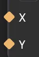
They accept the same data types as regular, circular sockets, but they are used to represent a special type of data flow.
Diamond sockets are contextful, meaning that the data they “hold” is determined by the context of the node they are connected to.
There are 2 types of contexts:
No Context
Section titled “No Context”A default context (CPU), which is the only context for circular sockets. A property socket with this context represents a single value of the specified type.
GPU Context
Section titled “GPU Context”Some Nodes such as Modify Image Node expose a GPU context. In GPU context, the property socket with diamond shape work per pixel. This means that there is no a single value for the property, but rather a formula that is applied to the pixel that is being processed.
Let’s take a look at this example:
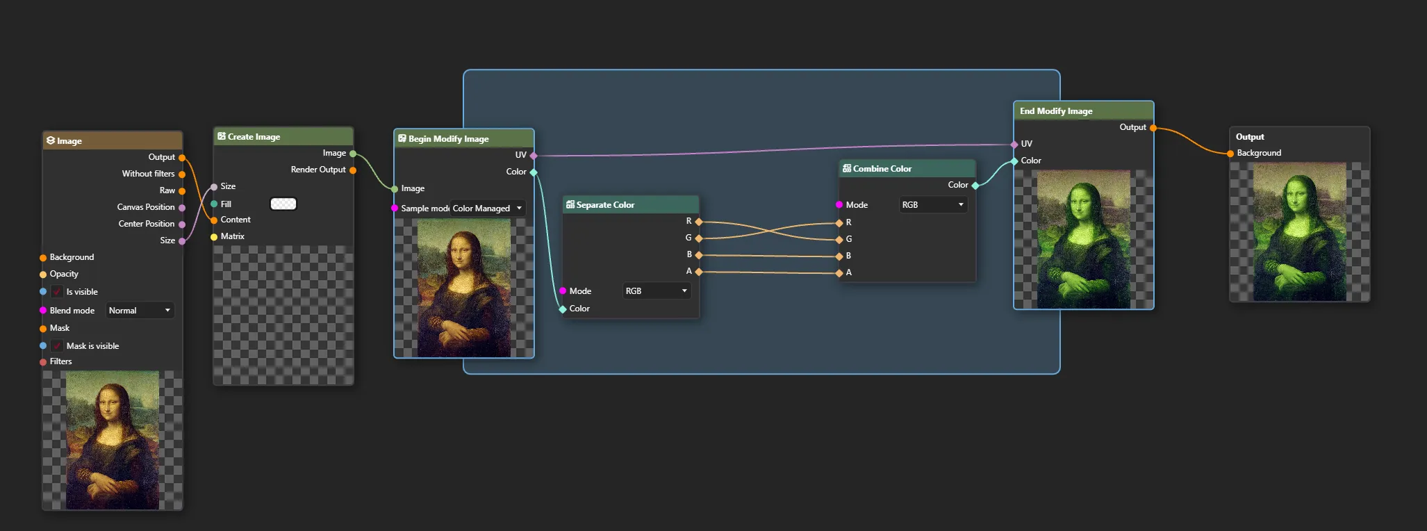
In this example, we’re modifying the Mona Lisa image with Modify Image Node. This node exposes 2 diamond-shaped sockets:
UVColor
Notice how Modify Image Node consists of 2 parts: Begin and End with blue zone between them.
There are also 2 Nodes connected to Modify Image: Separate Color and Combine Color. Essentially, in this example, we are swapping red with green channel of the image.
A Color is not a single value, but it points to a color of currently processed pixel. The UV is a coordinate of the pixel in the texture, which is being processed. It’s essentially a one big loop.
Imagine it processes a very first pixel of the image (top-left corner). The Color would be equal to #647360 ■ and UV would be equal to (0, 0). Then Separate Color Node would
return:
R= 100G= 115B= 96A= 255
Finally, the Combine Color Node would take these values and swap them, resulting in:
R= 115G= 100B= 96A= 255
This color value and the UV are passed to the End Modify Image, which puts the modified pixel back to the texture at the same UV coordinate (0, 0).
Then it processes the next pixel to the right, and so on until it reaches the end of the image.
Mixing GPU and CPU Contexts
Section titled “Mixing GPU and CPU Contexts”You can connect circular sockets to diamond sockets and vice versa. But you need to be careful about the context:
| Context flow | Behavior |
|---|---|
| CPU -> GPU | ✅ Single value is passed to GPU context, it doesn’t change. |
| GPU -> GPU | ✅ Normal GPU data flow. Value dependend on the context |
| GPU -> CPU | 🚫 Not allowed! Context data can never leave GPU context. |
Diamond socket can act the same as circular socket, if it is used in CPU context, but circular socket can never become GPU context aware.
GPU context is basically a Shader. Modify Image Node generates a shader code out of connected Nodes and their properties
Implicit conversions
Section titled “Implicit conversions”Some property types can be implicitly converted from one type to another. If the connection is possible, a noodle (line) connecting both sockets will become a gradient line, that starts with the color of the source socket and ends with the color of the destination socket.
Multi value to single value
Section titled “Multi value to single value”A VecD can be implicitly converted to a Float (or any single numeric value) by taking the first value of the vector.
(10, 20) -> 10 (10, 20, 30) -> 10
Single value to multi value
Section titled “Single value to multi value”A Float (or any single numeric value) can be implicitly converted to a VecD by creating a vector with X and Y values equal to the float value.
For VecD to Vec3D conversion, the Z value is set to Y value (X, Y, Y).
(10) -> (10, 10) (Double -> VecD)(10) -> (10, 10, 10) (Double -> Vec3D)(10, 20) -> (10, 20, 20) (VecD -> Vec3D)Test your knowledge!
Section titled “Test your knowledge!”Can you connect diamond socket to a circular socket?
What is the value of a integer input, when you connect VecD (12.44, 77.2) output to it?
All of our content is carefully written by hand, no AI was involved during the process.